Visible to Intel only — GUID: ofb1628558339934
Ixiasoft
1. Power Distribution Network
2. Gigahertz Channel Design Considerations
3. PCB and Stack-Up Design Considerations
4. Device Pin-Map, Checklists, and Connection Guidelines
5. General Board Design Considerations/Guidelines
6. Memory Interfacing Guidelines
7. Power Dissipation and Thermal Management
8. Tools, Models, and Libraries
9. Reference Designs and Development Kits
10. Document Revision History for AN 958: Board Design Guidelines
4.1. High Speed Board Design Advisor
4.2. Complete Pin Connection Table by Device
4.3. Pin Connection Guidelines By Device
4.4. Design for Debug with JTAG Pins
4.5. Hot Socketing, POR and Power Sequencing Support
4.6. Implementing OCT
4.7. Unused I/O Pins Guidelines
4.8. Device Breakout Guidelines
4.9. Additional Resources
5.1.1. Material Selection and Loss
5.1.2. Cross Talk Minimization
5.1.3. Power Filtering/Distribution
5.1.4. Unused I/O Pins
5.1.5. Signal Trace Routing
5.1.6. Ground Bounce
5.1.7. Understanding Transmission Lines
5.1.8. Impedance Calculation
5.1.9. Coplanar Wave Guides
5.1.10. Simultaneous Switching Noise Guidelines
Visible to Intel only — GUID: ofb1628558339934
Ixiasoft
5.1.3.1. Filtering Noise
To diminish the low-frequency (less than 1 kHz) noise caused by the power supply, filter the noise on the power lines at the point where the power connects to the PCB and to each device. You may place a 100-μF electrolytic capacitor adjacent to the location where the power supply lines enter the PCB. If using a voltage regulator, place the capacitor immediately after the final stage that provides the VCC signal to the device(s). Capacitors not only filter low-frequency noise from the power supply, but also supply extra current when many outputs switch simultaneously in a circuit.
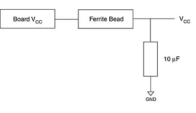
Another way to filter power supply noise is to place a non-resonant surface-mount ferrite bead, big enough to handle the current, in series with power supply. Place a 10-μF to 100μF bypass capacitor next to the ferrite bead (refer to Figure 16). Proper terminations, layouts, and filtering in a design eliminate the need for the ferrite bead. In this case, use a 0-Ω resistor instead of the ferrite bead.
Figure 16. Filtering Noise with Ferrite Bead
PCB elements add high-frequency noise to the power plane. To filter high-frequency noise at the device, place decoupling capacitors as close as possible to each VCC and ground pair. Placing the power and ground planes in parallel and separated by dielectric material provides another level of bypass capacitance. These parallel planes reduce the power-related high-frequency noise, since this type of capacitance has no effective series resistance (ESR) and no lead inductance.